Sensors
Often when we build devices we want them to react to the external environment. This means we have to implement some sort of sensor to detect the changes.
In this case we'll build a simple light detector. To understand this circuit you will need a little electronics background. We like current. Current gives power to lights, motors, speakers, and pretty much everything we need to run.
However, resistance is like the ogre that lives under the bridge. Every time somebody wants to pass, it requests a toll. A larger resistance means less current flows and the less bright our LEDs are. The exact equation is:
V = IR
However, a Light Dependent Resistor (LDR) is like an ogre that is afraid of light. The brighter it is, the smaller the resistance it has.
A tiny little problem here is that if we place an LDR in series with a battery, no matter how bright the environment is, the voltage will be 5V on one side and 0V on the other side. What if we wanted 3V on the other side?
Clues:
- You will need to wire up a LDR and a resistor
- Current in a series circuit is constant
- Voltage starts at +5 at one end and must be 0 at the other end
- Resistances add up when the resistors are joined from end to end
Well since we know that we can add up resistances, let's do that first.
R = R1 + R2
So imagine the entire thing is one giant resistor. Some current flows through it.
V = IR
V = I (R1 + R2)
But wait. Something interesting is happening here. We know V = IR . So this means that if we expand the equation...
V = I R1 + I R2 = V1 + V2
So the voltage across each resistor adds up to the total voltage. Now if the resistance of R1 increases, then this also means that V1 should increase. Now we have a relation between voltage and ambient light! If we can measure the voltage across R1 (our LDR in this case), we can actually tell how much light is falling on the resistor.
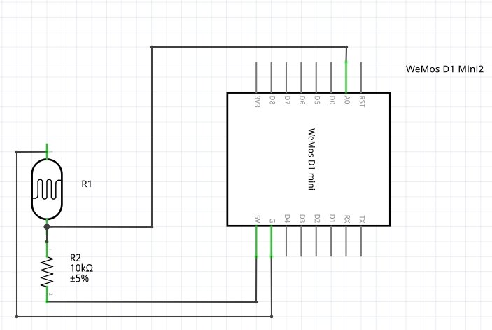
Figure 1. Schematic
The pin at A0 tells us the voltage after the LDR. Under brighter conditions, the resistance across the LDR falls and hence the voltage across the LDR falls accordingly and A0 reads a higher value.
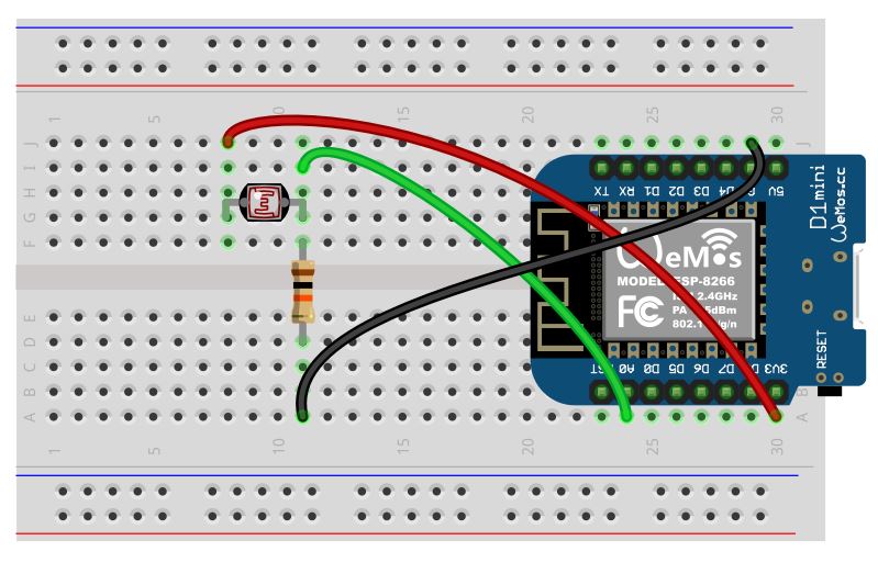
Figure 2. Wiring Diagram
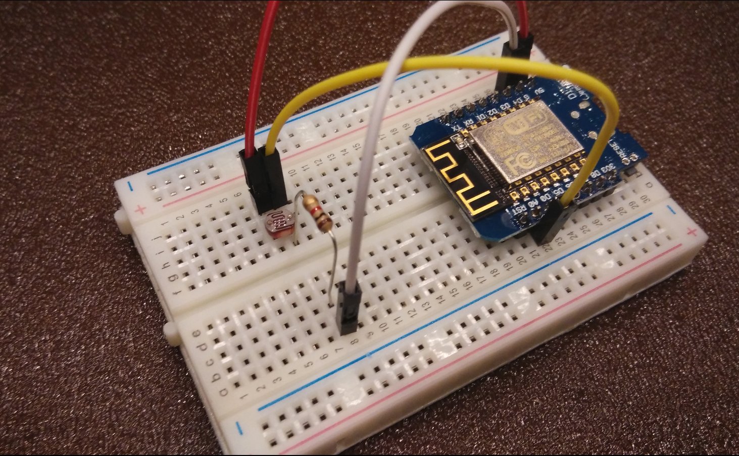
Figure 3. Wiring picture
If you flipped the position of the resistor and the LDR, the signal to A0 will then be flipped. It will read a low value in a bright setting, and a high value in a dark setting. Hence being able to estimate or determine voltages is very useful in predicting outputs and programming accordingly
Note that you'll have to scale depending on the brightness of the place you are using the circuit in. To get greater sensitivity in brighter settings, decrease the resistance in series with the LDR, and vice versa in darker settings.
Why are we using an analog input? Well since our other pins are digital, they can only sense if an input signal is HIGH or LOW. That is not in general very useful to us.
Programming
As usual we want to define our pins:
pinMode(A0,INPUT);
Now we want to use the Serial library to learn what our little sensor is detecting. A library in general refers to a set of programs or functions stored externally in a file, which you can use in your own program without having to write the programs or functions yourself.
This is sort of like visiting a library and pulling a book out to quote a line or copy an equation. So instead of having to write that entire book yourself, you can simply refer to the quoted material as "Book of Math, page 4, line 6". It is very convenient and this process makes for a cleaner program.
By default the Serial library is included, but not all libraries are, so sometimes we will have to define libraries. We'll not worry about that now, instead, within setup include:
Serial.begin(9600);
This sets up serial communications and the speed at which signals are sent is defined within the brackets. Now open the serial window by clicking the button at the top right corner of your Arduino program and check the 'baud rate' is the same as what you have defined. Sometimes if you receive gibberish in the Serial window, it is usually because the baud rates are different.
I wish to set up a constant to store my read values, and this is defined before setup:
float light_level;
float is a type, much like how int is a type. It is able to store more data, and can process decimal points.
ints and floats are usually used for numbers. If you wanted to display a character, it would be char:
char my_word='d';
Note that if you define new values in setup, the system will not be able to use it in loop because it is not global, or usable by both loop and setup. You can only do so if you define values outside of either.
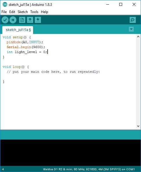
Figure 4. Wrong location to define new varibles
You want to read the pin A0 and assign it to light_level so that you can print it out to the Monitor. This is not strictly necessary, but it makes for easier reading of the code.
Now let's read our values and print them every second:
Serial.println(light_level);
Serial.println("Println in action!");
Serial.print(light_level);
Serial.print("Print in action!");
delay(1000);
Your code should be the following:
float light_level; // global variable

void setup () {
  pinMode(A0,INPUT);
  Serial.begin(9600);
}
void loop() {
  light_level = analogRead(A0);
  Serial.println(light_level);
  Serial.println("Println in action!");
  Serial.print(light_level);
  Serial.print("Print in action!");
  delay(1000);
}
Bring up the Serial Monitor by clicking on the little magnifying glass icon on the top right, highlighted in red in the picture below:
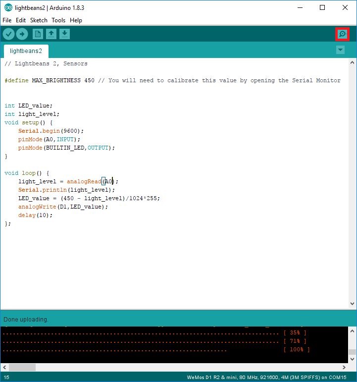
Figure 5. Serial Monitor
Now if you selected the wrong Port or did not connect your chip, the following might show:
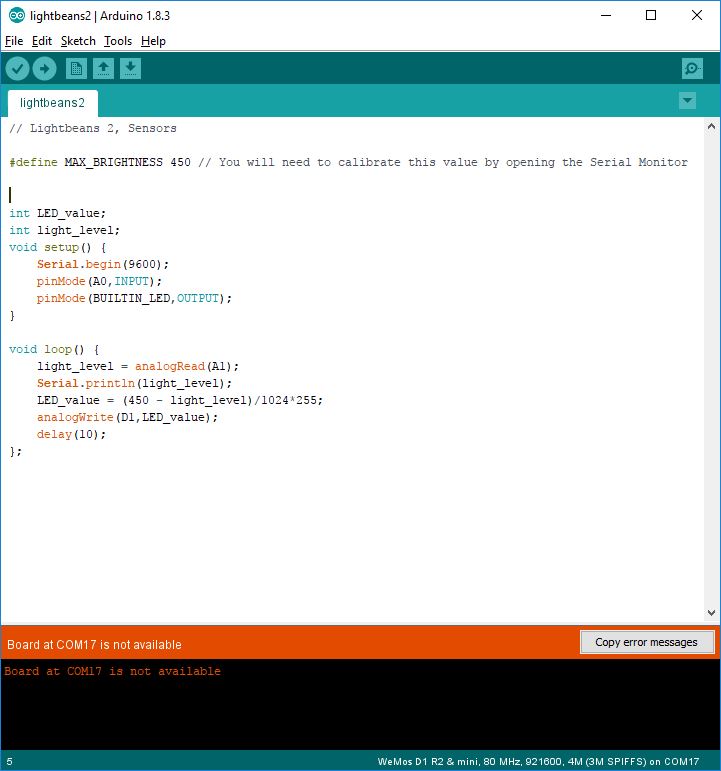
Figure 6. Serial Monitor Error, not connected
Under Tools > Port make sure that the right port is selected.
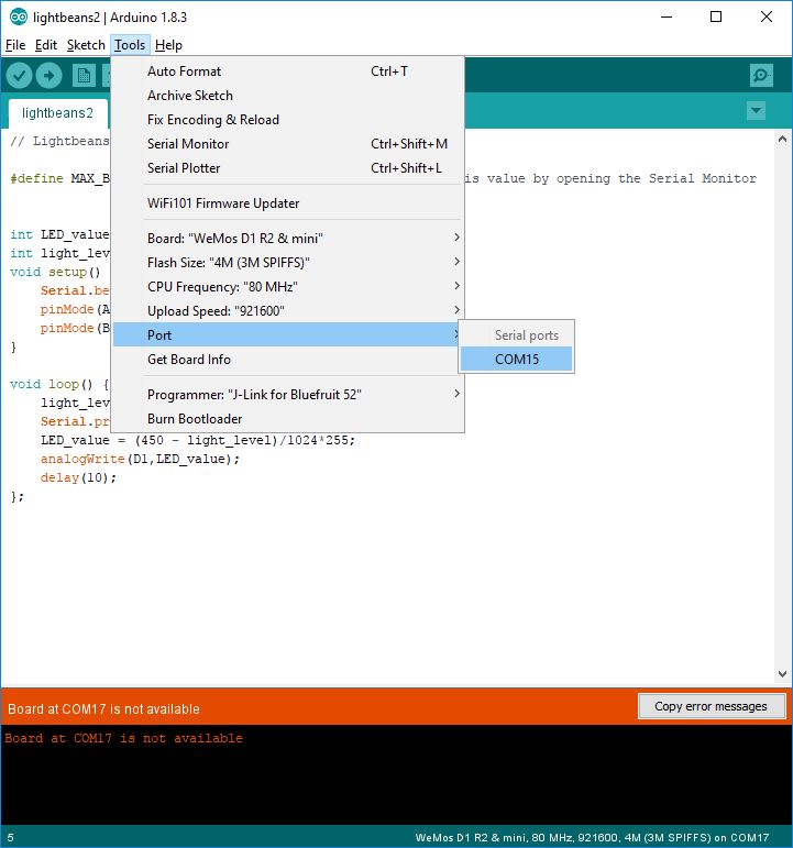
Figure 7. Selecting port
You should see the following output, although your numbers might be different:
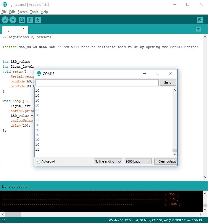
Figure 8. Serial output
What do you notice? With println the output is printed on each new line while print prints on the same line. This is useful for formatting the output on the serial and other interfaces
Now if you shade the LDR, the values should drop and when you put it under light, the values should go back up.
More LEDs!
Now we want to do something to this data we are getting. Looking back on our original LED program, can you come up with a program that lights up an LED after a certain brightness threshold?
We want to write this value to the LED. Analog inputs are scaled from 0 to 1024, but our LED only scales from 0 to 255 so we need to modify this a little:
LED_value = light_level/1024*255;
Note that since we are doing division, we have to use a new type of value called float. This is important because although int can store huge numbers, it cannot handle decimal point numbers or fractions. This means that if it gets a fraction, it automatically rounds it down to the lowest number. So here we will always get zero if we use ints.
float LED_value;
float light_level;
However this only works if you have set up your LED such that it senses from 0 to 1024. However, most setups only go up to a certain value, say 300 to 500, so determine the maximum value you can read by putting the LEDv as close as possible to the light source. So, above setup:
#define MAX_BRIGHTNESS 450.0 //maximum value read
A #define is used when a value is constant in the sketch. It is useful if you want to adjust values, because now you only have to change it in a central place. Note that you can also indicate a value is a float by adding a decimal point.
To make it a little more interesting let's make our LED light up when it is dark:
LED_value = (MAX_BRIGHTNESS - light_level)/1024.0*255;
The value of 450 was determined through a little trial and error. This is the largest value you should be able to read in your environment and setup. If the value you determined is too low, a negative value will be given to the LED and this essentially means that it counts backwards from 255, so you might actually see your LED suddenly become brighter after dimming!
Remember to define any new constants you use!
Sketch
// Lightbeans 2, Sensors

#define MAX_BRIGHTNESS 450.0 // You will need to calibrate this value by opening the Serial Monitor

float LED_value;
float light_level;
void setup() {
    Serial.begin(9600);
    pinMode(A0,INPUT);
    pinMode(BUILTIN_LED,OUTPUT);
}

void loop() {
    light_level = analogRead(A0);
    Serial.println(light_level);
    LED_value = ((MAX_BRIGHTNESS - light_level)/1024.0)*255.0;
    Serial.println(LED_value);
    analogWrite(BUILTIN_LED,LED_value);
    delay(1000);
}
What you learned
- Analog inputs.
- Using sensors to drive outputs.
Libraries
In your package you will have a ring of tiny white chips with three wires sticking out. This is a Red-Green-Blue (RGB) Integrated Chip. It combines three small but bright LEDs into a neat little package and by using some clever signalling, these LEDs can be made to generate any color you want within the spectrum. They are also known as WS2812b LEDs or Neopixels.
In this lesson, we will be using Adafruit's NeoPixel library. If you don't know how to install a library yet, the Arduino website provides a good guide to getting up and running quickly.
As described earlier, learning how to use libraries is important. For this chip, it requires an extremely specific sequence of signals to be sent. Luckily, Adafruit has already done the hard work for us and we can use the functions they have wrote!
If you run across a new device you'd like to use try searching online for libraries. Arduino has huge community support for many devices.
Programming
In order to use the library to run our pixels, we have to include it as follows (after installation!):
#include <Adafruit_Neopixel.h>
A new way of defining variables is as follows:
#define NUMPIXELS 1
#define PIN D6 // connect to D6 of ESP8266
This is useful if you want to give a constant value a name. Naming your variables adds clarity and simplicity to your program. You can now also change variables in a common plac, reducing chances of possible mistakes. Here we have defined D1 as the variable PIN. When the program is compiled, it will replace all occurances of PIN with D1.
Next we want to set up our configuration for our 5050 chip. This should be included under setup.
Adafruit_NeoPixel pixels = Adafruit_NeoPixel(NUMPIXELS, PIN, NEO_GRB + NEO_KHZ800);
Now to break this down a little, Adafruit_NeoPixel refers to the type of value we are dealing with. This is similar to int or float. In this case, we are telling the IDE that "pixels" is a "Adafruit_Neopixel" object. This is like telling the IDE, "Please go to this new shelf I just installed, and take out a book about pixels."
It requires two variables: the number of pixels we are using and the pin number to output the signal on. We also have to specify the protocol, but we don't have to worry about it in this instance.
Now when we want to use our LED, we merely have to refer to pixel.
The way we use the chip is that we define the 5050 chip that we are lighting up, then the colors, and finally we show them. It is like priming each pixel with a preset value before turning them all on simultaneously.
pixels.setPixelColor(0,pixels.Color(155,155,0));
pixels.show();
setPixelColor is a function that takes the the number of the chip in series you want to modify, and the color you want to modify it to as an RGB value. show takes no values and changes the color of the LED to the one you just defined.
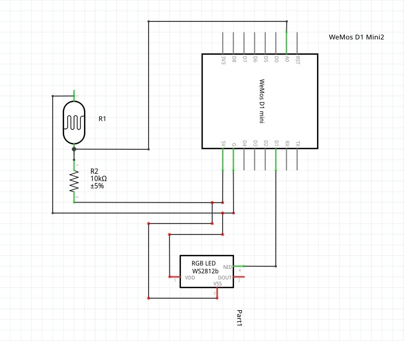
Figure 1. Schematic
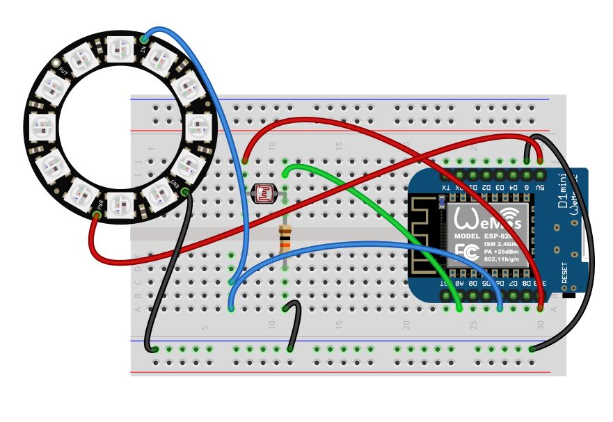
Figure 2. Wiring
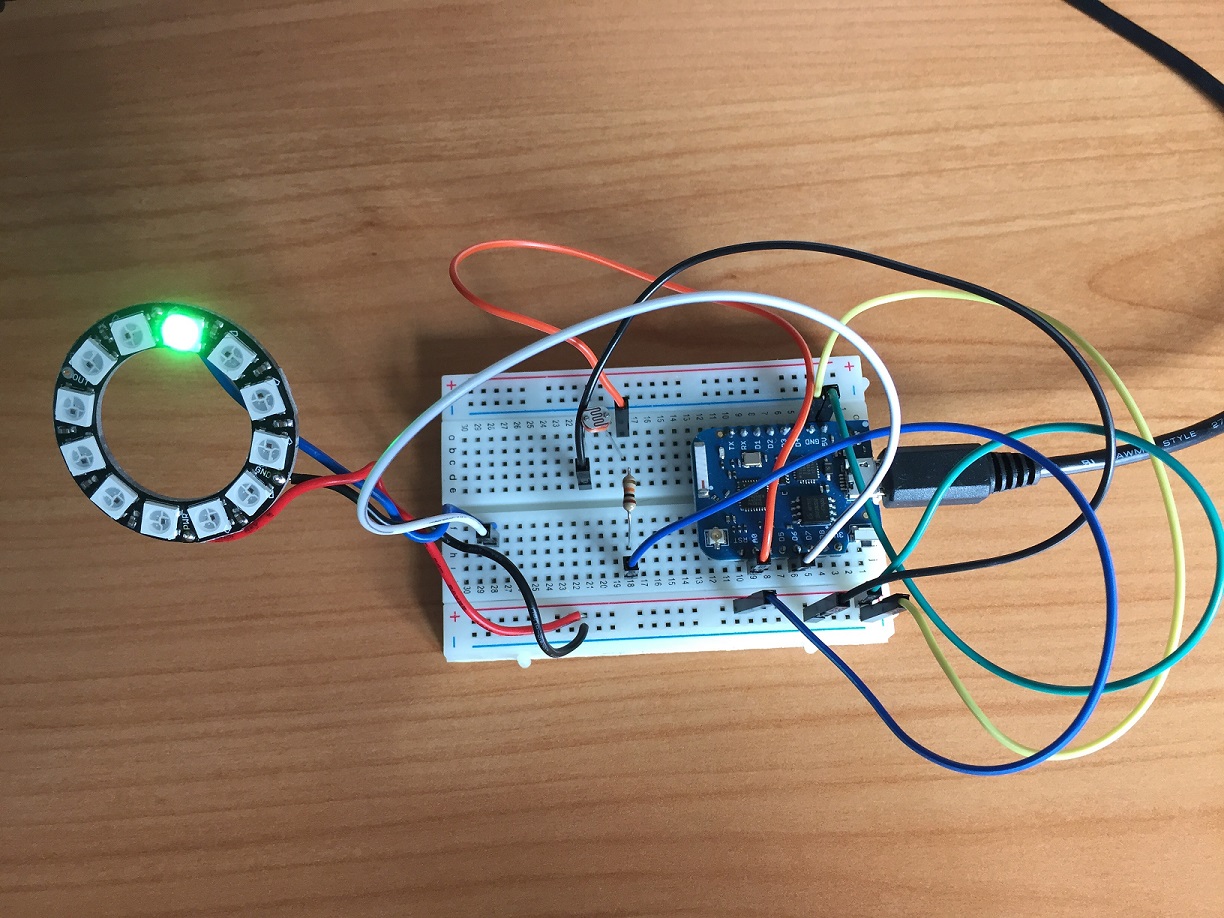
Figure 3. Wiring picture
Now you do something fun to scale the colors according to input. Knowing that each RGB value is from 0 to 255, we can use a linear scale from 0 to 765 to pick a color. Mixing two colors is more fun than having just red, green or blue, so as one color fades, we can make color brighten. Scaling our analog input to the range of 0 to 1023 (because this is the range of values that the sensor can read), we can then display a range of colors dependent on our input.
Figure 4. Lighting in action
Sketch
#include <Adafruit_NeoPixel.h>
#define NUMPIXELS 12 // Set this to the number of pixels you have
#define PIN D6
#define INPUT_PIN A0 // config for ESP8266
#define MAX_BRIGHTNESS 400.0


int r = 0;
int g = 0;
int b = 0;
float input_value;

Adafruit_NeoPixel pixels = Adafruit_NeoPixel(NUMPIXELS, PIN, NEO_GRB + NEO_KHZ800);
void setup()
{
    Serial.begin(9600); // config for ESP8266
    pixels.begin();
}


void loop()
{
    input_value = analogRead(INPUT_PIN);
    Serial.println(input_value);
    input_value = ((MAX_BRIGHTNESS-input_value)/MAX_BRIGHTNESS) * (3*(255));
    //Serial.println(input_value);
    if (input_value<255){
        r = input_value;
        g = 0;
        b = 0;
    }
    if (input_value <510 && input_value>255){
        r = 510 - input_value;
        g = input_value-255;
        b = 0;
    }
    if(input_value>510){
        r = 0;
        g = 765-input_value;
        b = input_value-510;
    }
    pixels.setPixelColor(1,pixels.Color(r,g,b));
    pixels.show();
    delay(10);
}
FAQ
- Help! My 5050 chip doesn't light up!
Check that you are connected to the right pins and all leads are secured. Some unexpected values are caused by loose leads.
Check that your resistor value is high enough. One way is to test the values in the
setup. If the resistor value is too low/too high the output will be 0 or 1024.Check that you have put your photo-transistor in the right direction. The long lead of the photo-transistor goes to
GND. - Help! It is still not working!
Check for crossed leads and test the LED with a single value instead of a variable. If it still doesn't light up, please contact us for a replacement.