Introduction and Installation
This is the first project of ULCEK. In this project, you will be building a night light and learning a basic introduction to the world of Arduino and electronics.
There are a few things that are required before we begin the project:
- Install the Arduino IDE
- Board Definition Installation for the WeMos Mini
- Driver Installation for CH340G (WeMos Mini) Windows or MacOS
- Driver Installation for CP2104 (WeMos Mini Pro)
Install the Arduino IDE
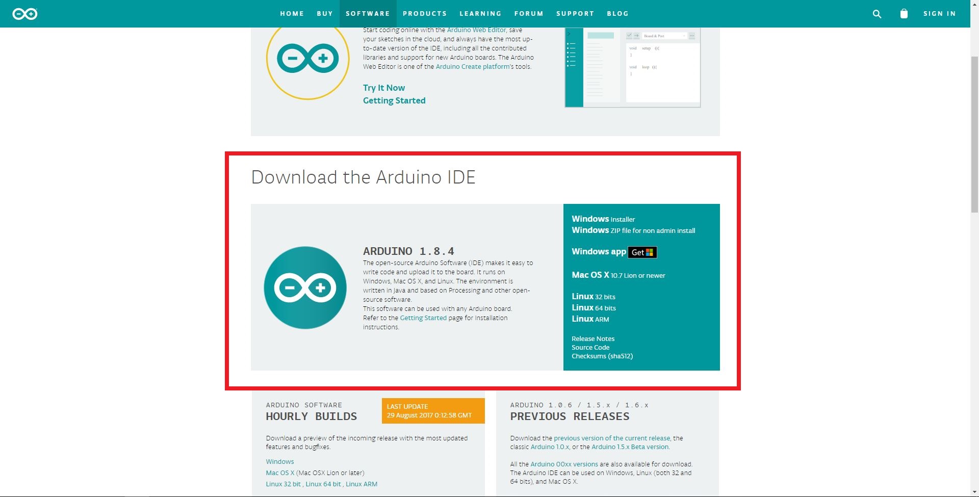
Figure 1. Installing Arduino IDE
Board Definition Installation for the WeMos Mini
Open Arduino, go to File > Preferences
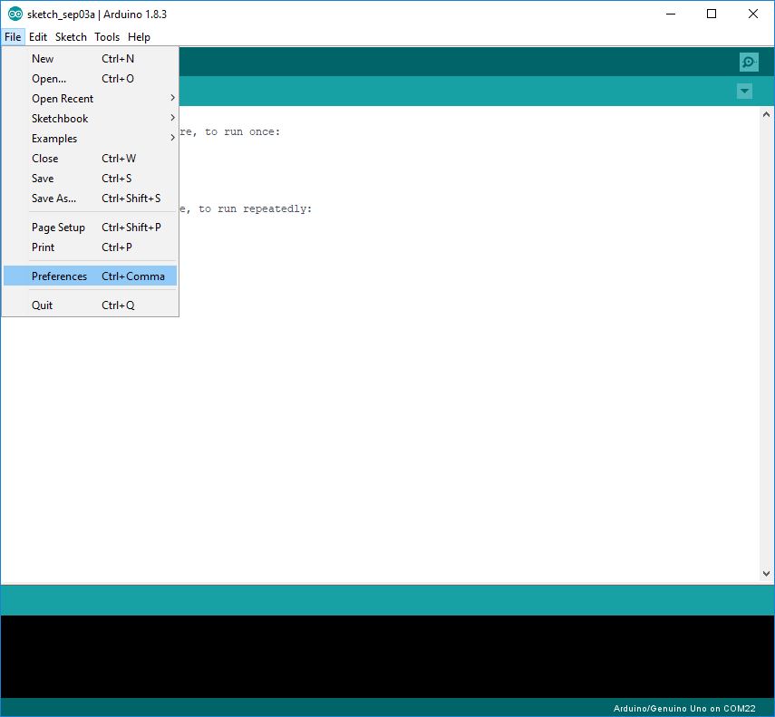
Figure 2. Preferences
Under Additional Boards Manager URLs, paste in this address: http://arduino.esp8266.com/stable/package_esp8266com_index.json
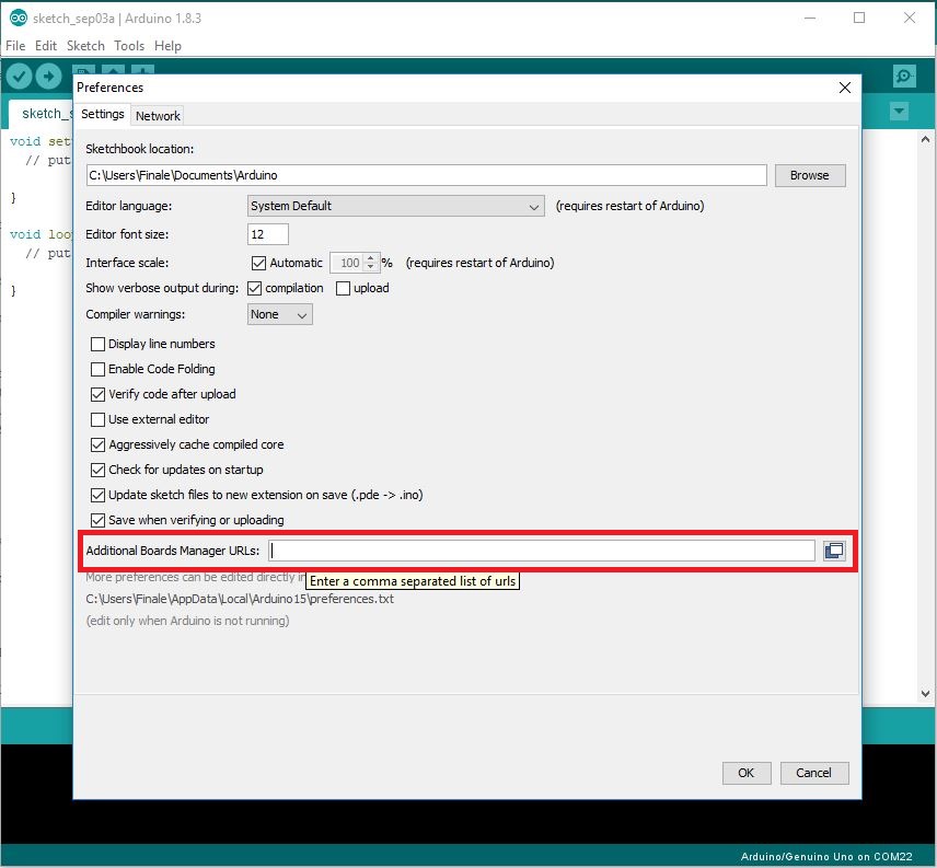
Figure 3. Additional Boards Manager URLs
Installing the CP2104 Driver
If you have the following chip, you will install the CP2104 driver.
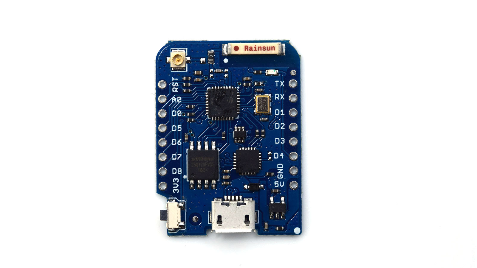
Figure 4. WeMos Mini Pro
Go to the following address: https://www.silabs.com/products/mcu/Pages/USBtoUARTBridgeVCPDrivers.aspx and download the default drivers. If you have a MacOS or Linux system, the drivers are already included. Windows 10 also includes the drivers.
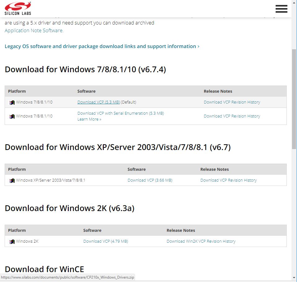
Figure 5. Installing Drivers
Once you have installed everything, you should be able to plug in your board and see it as a port in Tools > Ports.
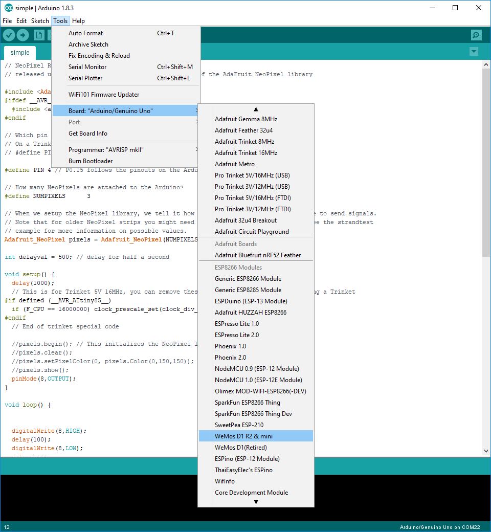
Figure 6. Selecting your board
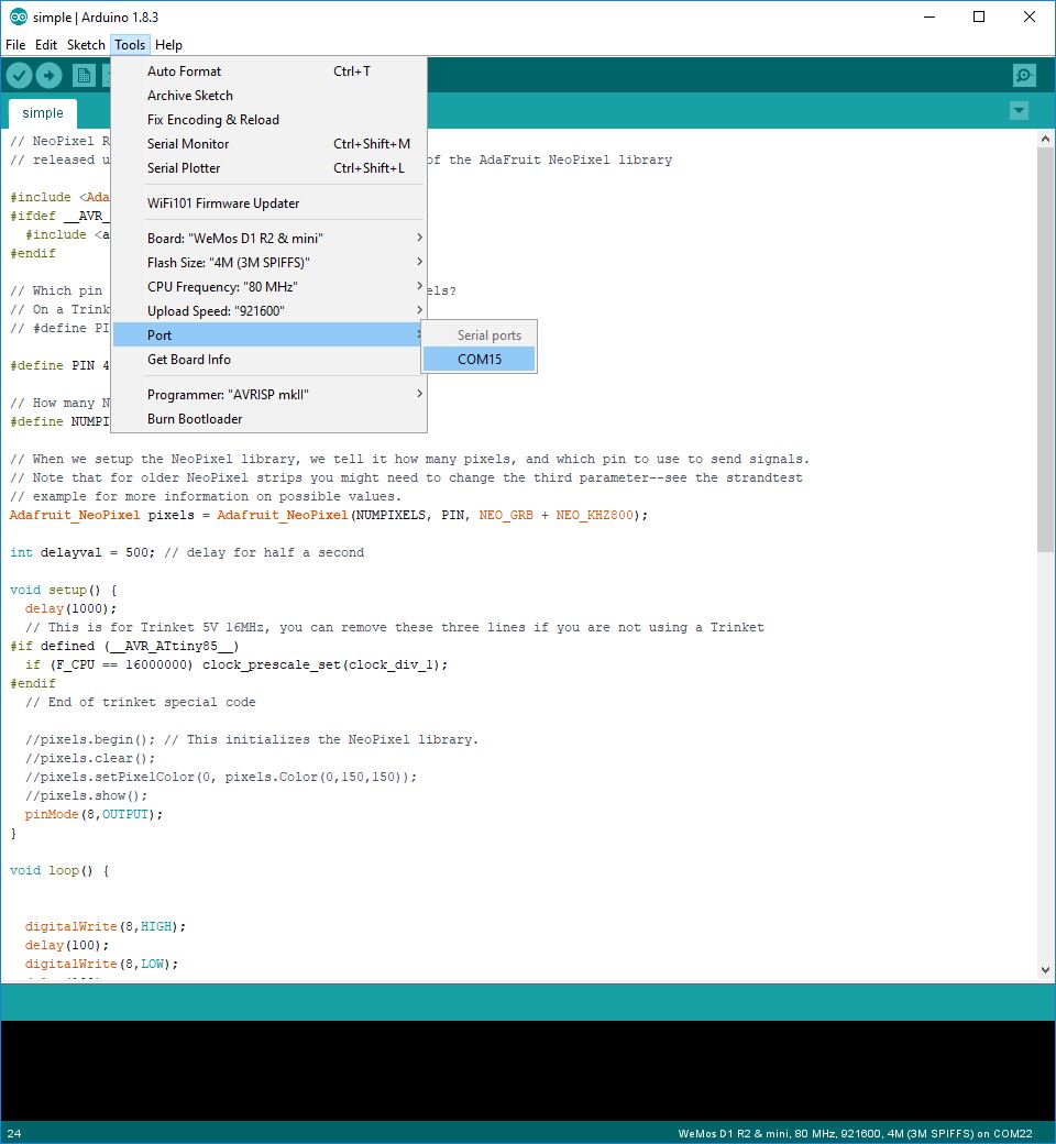
Figure 7. Selecting the port
FAQ
- Help! The Port option is greyed out!
This occurs when the device is not detected by Arduino. Try reinstalling the drivers, restarting the Arduino IDE. If that does not help, try restarting your computer. - Help! The Port option is still greyed out!
Try using a different USB cable and a diferent ports. USB cables that are used to transfer data such as photos to the computer are a good choice. Some USB cables only transfer power and so do not work when trying to program the board. Some ports are mounted differently and where one port doesn't work, another might, especially for MacOS systems. - Help! I don't see
WeMos D1 R2 & Miniunder Board
Install the board definitions as described above.
Programming
Following the time-honored tradition of all guides, a blinking LED will be your "Hello World!" for electronics. Here we will use the LED on the board.
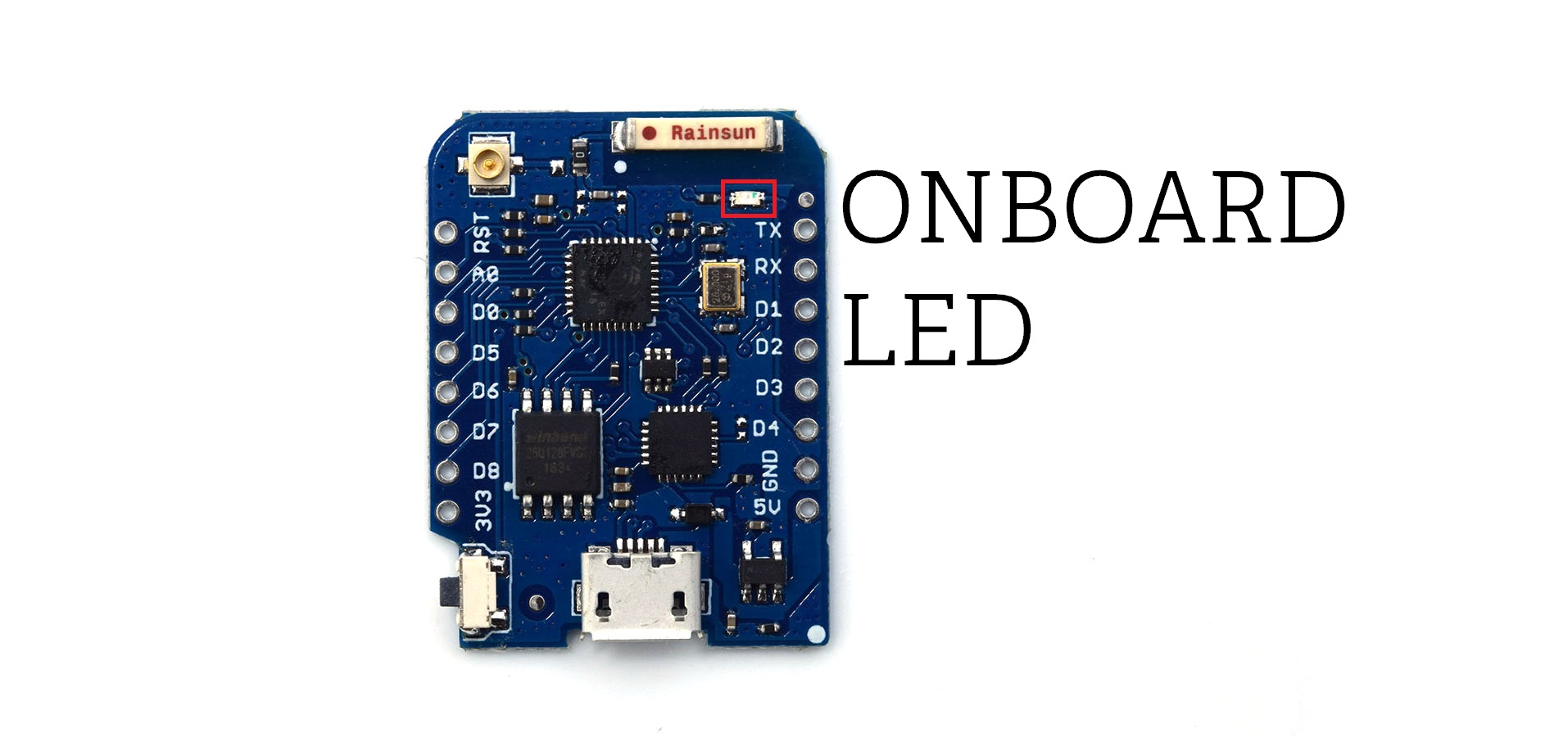
Figure 1. On Board LED
You are using a microcontroller to interact with the LEDs. A microcontroller is essentially a tiny computer that runs one program.
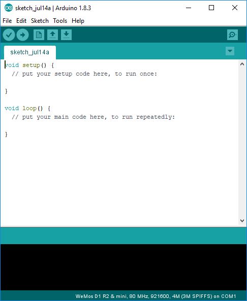
Figure 2. Initial opening of Arduino IDE
When you first start the Arduino program, notice that there are two lines, one which is the setup, and the other will be the loop. The curly brackets {} are limits to show what lines does setup or loop contain.
When it starts, the microcontroller will run all the commands in setup once, and then run the commands in the loop. When it reaches the last command in loop, it will then restart the cycle until it is powered off. The setup will be where we declare to the microcontroller what pins we are using and the loop will instruct the microcontroller what to do in each cycle.
In Arduino, we use pins to send and receive data. These are the little pointy things on the Nano or WeMos that plug into the breadboard. By sending data to these pins, we can control other electronics components.
We'll have to declare to the microcontroller that we are using the onboard LED. Enter the following between the braces {} after setup.
pinMode(BUILTIN_LED,OUTPUT);
pinMode is the function that helps us to declare what the pin is going to be. But we have to give it two inputs: the pin number, and what the pin is functioning as. The onboard LED on the board has a reference of 1, so we are going to use 1 to refer to it. Since we are sending a signal to this pin, we are going to use it as an OUTPUT. You will see Arduino highlight OUTPUT in blue because it is a keyword. All blue words serve a specific use and should not be used as variables.
Some variables are already defined. In some cases we can also use BUILTIN_LED to specify the onboard LED for the ESP8266. This has already been defined for us elsewhere in the code. You can also use the numbers printed next to the pins to determine which pin will be activated.
Remember to add ; after you complete a command. This acts as a delimiter, much like how spaces in sentences help to form words. Without it the IDE will not be able to understand whatyouaretryingtosay.
In the following code below I will be using comments. These are parts which the program does not read and you'll see them to be grey-ed out. They are anything that follows // on that line. If you remove the // the code will be read by the Arduino IDE again. This is useful in adding comments to clarify what your code is doing as well as to test your code.
Great! Now how shall we blink our LED? One second off, two seconds on? In the loop portion of our program, write the following:
digitalWrite(BUILTIN_LED,LOW);
delay(1000); //delay counts in miliseconds
That settles the off portion of our loop, can you guess the on portion?
digitalWrite(BUILTIN_LED,HIGH);
delay(2000); //delay counts in miliseconds
Never had any doubt in you. delay as you might have guessed, stops the microcontroller. digitalWrite tells a specified pin to go either HIGH or LOW, and this physically means that it turns a pin on or off.
While you are typing your code, you can space out your words to make them more readable.
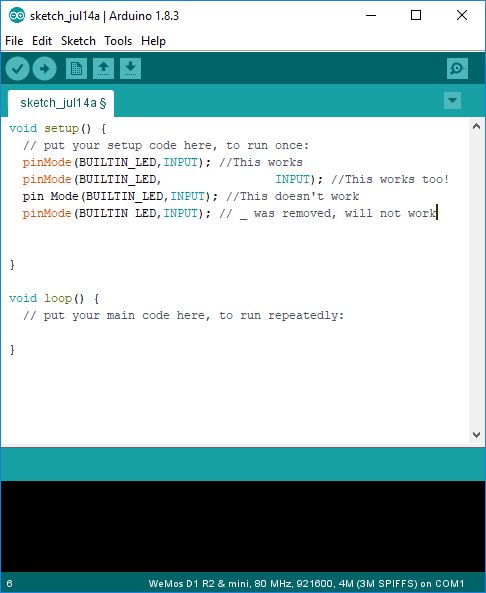
Figure 3. Whitespace Examples
Now plug in your chip and click the upload button!
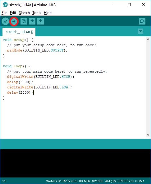
Figure 4. The upload button is highlighted in red
You should see the LED on your board start to blink
Sketch
//#define BUILTIN_LED D4 //for the ESP8266
//#define BUILTIN_LED 13 //for the Nano
#define OFF_TIME 2000 // time which it is off
#define ON_TIME 2000 // time which it is on

void setup()
{
    pinMode(BUILTIN_LED,OUTPUT);
}
void loop()
{
    digitalWrite(BUILTIN_LED,HIGH);
    delay(ON_TIME);
    digitalWrite(BUILTIN_LED,LOW);
    delay(OFF_TIME);
}
FAQ
-
Help! I have a Mac and it doesn't work!
Try using a usb extension or a USB-2 port. The USB ports of the newer Macs are recessed and the data pins might not touch. Trying different USB ports might also work.
Check that it isn't a driver issue. If it is, please look up on how to install a CH340G or CP2104 driver for your particular configuration.
-
Help! The compiler is giving me an error!
Did you complete braces
{}, use()and all delimiters;? -
Help! How do I upload code?
For the Digispark, upload the code first, then plug it in. For the WeMos and Arduino Nano board, plug it in then upload your code.
-
There is an espcomm error!
Ensure that you have selected the correct port.
-
There is still an espcomm error!
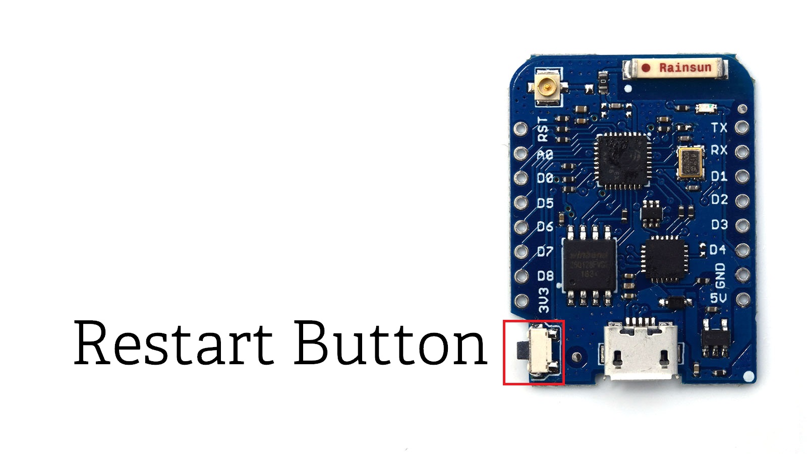
Press the restart button on the side of the board until just before the IDE starts to upload (when
Uploading...appears in the status beside the progress bar). Sometimes the board is running code and doesn't notice that you want to upload new code.
What you learned
-
How to define output pins.
-
How to upload a sketch.
-
How
digitalWriteworks. -
How
delayworks.
Additional Projects
-
Can you change the period that the LED blinks?
-
Can you change pattern that the LED blinks?