Extracting Code
In this series of tutorials, we will utilize the wifi-capabilities of the ESP8266 chip and talk to the internet.
We will first enable the Over-The-Air ability of our ESP8266 chip for future convenience. Please select your board under Tools > Board.
Plugging and unplugging the ESP8266 can be a hassle especially if you want to use it with a power source that is not your computer. Fortunately, the ESP8266 comes with an ability to update itself Over-The-Air (OTA). The board connects to an Access Point (AP) or router, and awaits instructions. Think of it as an invisible USB cable that is connected from your computer to your board via WiFi.
In this tutorial, we will learn how to extract useful code from other examples. This is a useful skill as you might only want some parts of a project to use in your own.
Now open File > Examples > ArduinoOTA > BasicOTA in a separate Arduino window. For this project we will use most of the code that is provided and explain what each part does.
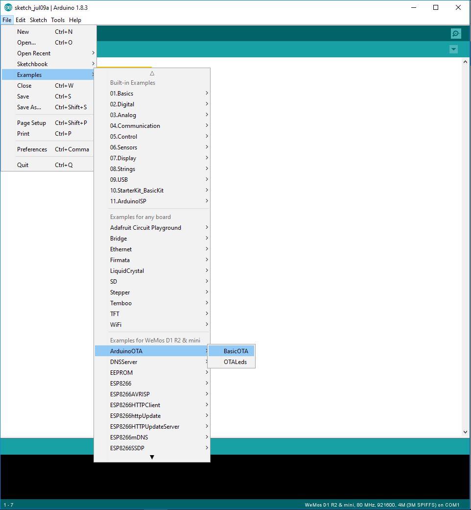
Figure 1. Arduino OTA
Now we will need to include a couple of libraries for our OTA to work:
#include <ESP8266WiFi.h>
#include <ESP8266mDNS.h>
#include <WiFiUdp.h>
#include <ArduinoOTA.h>
Now we want to give our chip the SSID (name) of the network and the password:
const char* ssid = "MyNetwork";
const char* password = "Password";
Now going into setup, we want to perform some startup procedures on our chip:
WiFi.mode(WIFI_STA); //we are going to be a client!
WiFi.begin(ssid,password); //Start the wifi, with this ssid and password
In order to ensure that some boot process didn't mess up our wifi chip, we are going to restart the WiFi chip if we didn't connect after awhile:
while (WiFi.waitForConnectResult() != WL_CONNECTED)
{
    Serial.println("Connection Failed. Rebooting ... ");
    delay(5000);
    ESP.restart();
}
Now we need some indicators to tell us if we are done and/or we faced errors. These functions that we call from ArduinoOTA tell us if we have started, ended, and what our progress is:
ArduinoOTA.onStart([]() {
  Serial.println("Start");
});
ArduinoOTA.onEnd([]() {
  Serial.println("\nEnd");
});
ArduinoOTA.onProgress([](unsigned int progress, unsigned int total) {
  Serial.printf("Progress: %u%%\r", (progress / (total / 100)));
});
The following code helps to diagnose the error if the connection is not made. It is very useful for debugging purposes.
ArduinoOTA.onError([](ota_error_t error) {
  Serial.printf("Error[%u]: ", error);
  if (error == OTA_AUTH_ERROR) Serial.println("Auth Failed");
  else if (error == OTA_BEGIN_ERROR) Serial.println("Begin Failed");
  else if (error == OTA_CONNECT_ERROR) Serial.println("Connect Failed");
  else if (error == OTA_RECEIVE_ERROR) Serial.println("Receive Failed");
  else if (error == OTA_END_ERROR) Serial.println("End Failed");
});
Now we have set up everything, it is time to start:
ArduinoOTA.begin();
Serial.println("Ready");
Serial.print("IP address: ");
Serial.println(WiFi.localIP());
The only thing you need to put in the loop is:
ArduinoOTA.handle();
So now that you have this bunch of code, you can add visual indicators that separate them from other code you don't when you are implementing it for other projects:
//============= Don't Touch This ==================
code code code
code code code
//============= End of Don't Touch This =============
Useful: Having visual sections for your code helps you to keep track of where you are better.
There you go! Now if you are coming from the Lightbeans tutorial, try changing the color of the light and uploading it wirelessly! If not, try changing the blink rate of the on board LED on the ESP8266 board.
You should find the ESP8266 listed as another port on your Arduino IDE if you are connected to the same network. Note that the OTA only works on your home network (you can't access it from the internet).
As long as you include this code on all your projects you should be able to update the ESP8266 wirelessly.
When you want to update the code on your ESP8266, select Tools > Port and you will see your board listed with a ip address.
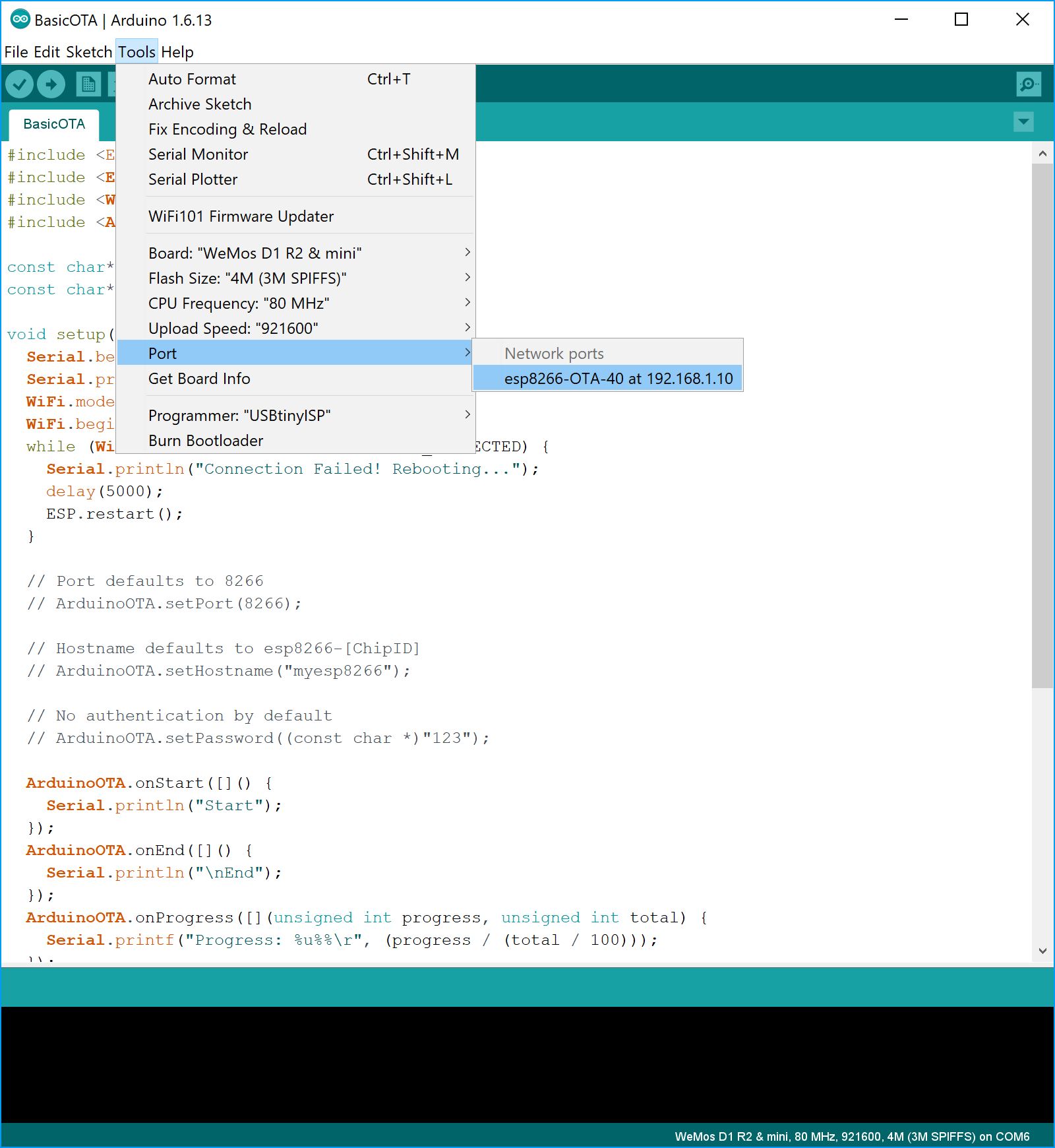
Figure 2. Arduino OTA Port
Sketch
#include <ESP8266WiFi.h>
#include <ESP8266mDNS.h>
#include <WiFiUdp.h>
#include <ArduinoOTA.h>

const char* ssid = "MyNetwork";
const char* password = "Password";

void setup () {
  WiFi.mode(WIFI_STA); //we are going to be a client!
  WiFi.begin(ssid,password); //Start the wifi, with this ssid and password

  Serial.begin(9600);

  // Wait for connection

  while (WiFi.waitForConnectResult() != WL_CONNECTED)
  {
      Serial.println("Connection Failed. Rebooting ... ");
      delay(5000);
      ESP.restart();
  }

  // Debug

  ArduinoOTA.onStart([]() {
    Serial.println("Start");
  });
  ArduinoOTA.onEnd([]() {
    Serial.println("\nEnd");
  });
  ArduinoOTA.onProgress([](unsigned int progress, unsigned int total) {
    Serial.printf("Progress: %u%%\r", (progress / (total / 100)));
  });

  ArduinoOTA.onError([](ota_error_t error) {
    Serial.printf("Error[%u]: ", error);
    if (error == OTA_AUTH_ERROR) Serial.println("Auth Failed");
    else if (error == OTA_BEGIN_ERROR) Serial.println("Begin Failed");
    else if (error == OTA_CONNECT_ERROR) Serial.println("Connect Failed");
    else if (error == OTA_RECEIVE_ERROR) Serial.println("Receive Failed");
    else if (error == OTA_END_ERROR) Serial.println("End Failed");
  });

  // Start process

  ArduinoOTA.begin();
  Serial.println("Ready");
  Serial.print("IP address: ");
  Serial.println(WiFi.localIP());
}

void loop() {
  ArduinoOTA.handle();

  // Code for project begins below

}
FAQ
- I don't see the port!
Restart your computer and the Arduino IDE.
- Arduino says that it cannot find python.exe!
Install Python and add it to your system envrionment variable or system path.
- It says that there is no response.
Make sure that python.exe is able to access the network. For Windows if you allowed it through a private network, then make sure your network category is private.
What you learned
- How to update your ESP8266 chip wirelessly.
- How to segment code visually.
- How to extract useful code from examples.
Additional Projects
- Remove all debugging code to make the OTA section as short as possible.
- Research how to give your ESP8266 a hostname
Interrupts
Now you might want to turn off the night light, so having a button would be useful for that.
Instead of asking the button if it has been pressed, we'll let the button come to us, metaphorically speaking.
The first method is called polling because we ask a sensor for data. However this method can be a little wasteful because we have to wait for the sensor to get back to us each time, and when there is no change for long periods of time, then this little waste builds up.
The second method is called interrupts because the chip is interrupted when there is a change in status. This is better as it allows the chip to react immediately when there is a change, and it can do other things if there is no change.
For our chip, we can attach an interrupt to a pin for our button. The interrupt will then call a function which we can then use to do whatever action we intend that interrupt to have.
Syntax
Firstly, the syntax for interrupts are as follows:
setup (){
  pinMode(interruptPin,INPUT); //interruptPin was defined earlier in the code
  attachInterrupt(digitalPinToInterrupt(interruptPin), buttonPress, FALLING);
}
We must first set the pin up as as input, then we must specify the pin we intend to interrupt, the function we want to call, and the type of interrupt.
The type of interrupt requires a little knowledge of signals, but you've already done this! The interrupt can detect when a signal changes, or the state of a signal. A table below summarises the types.
| Interrupt | Signal |
|---|---|
| HIGH | Triggers when signal is high |
| LOW | Triggers when signal is low |
| RISING | Triggers when signal goes from low to high |
| FALLING | Triggers when signal goes from high to low |
| CHANGE | Triggers when signal changes from either state |
Writing Interrupt Functions
Now let's write the button function:
void buttonPress(){
  state =! state;
}
Note that your function cannot take any arguments nor can it return any arguments. This is a special type of function. Because this function may be called at any time, having it interact with an argument might result in an unexpected outcome. That argument might not have been defined yet, or the value might have changed.
Note that arguments are not the same as global variables. Global variables are values that are initialised outside of setup or loop.
The equation =! is to set the variable the opposite boolean value that it was originally. If it were true, it will now become false and vice versa. This helps us turn the light on or off based on the same input (button press). It is the same to saying 'not', so for example 'not true' is false and 'not false' is true.
Any global variable an interrupt function uses must be specified as follows:
volatile bool state = true;
It must have the keyword volatile attached to it because it can change any time, and we have to let the program to know that.
The variable name state here is intentional. States can be any number of things: 1 to 10, true or false, happy or sad. However they all serve the same purpose, which is to keep track of where the system is at now.
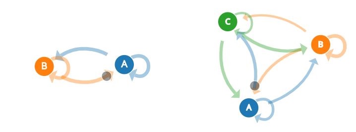
Figure 1. All possible transitions
Since state is a global variable we can include it in our Night Light code:
...
if (input_value < BRIGHTNESS and state==true){
  turnOn();
}
if (input_value > BRIGHTNESS or state==false){
  turnOff();
}
...
Now, wire it up as follows in the diagram below. Note that you should add this circuit to your existing circuit.
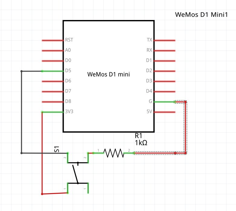
Figure 1. Circuit Schematic
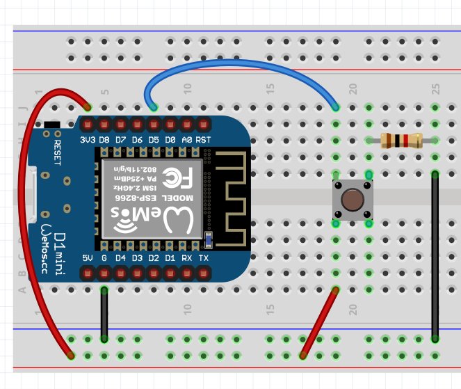
Figure 2. Circuit Layout
Why is there a need for the additional resistor? Well, when we are not pressing the button, we cannot leave it hanging, or it will read random data. Therefore, we have to bring it to zero when we are not pressing it. When we press it, we want to bring it to high (but it is still connected to ground!) so to prevent a short, we put a resistor there.
Now the pin reads a HIGH value on button press, and a LOW value when the button is not pressed. This is known as a pullup resistor and if you flipped the operation, that would be known as a pulldown resistor.
Two of the inputs of the button are connected to each other as seen in the diagram above, and they can be identified because the legs stick out slightly in the same direction for the connected corners. If your button doesn't work on the first go, try rotating it by 90 degrees.
Excellent! Now when you upload your code, you should be able to turn off your nightlight at will. Turning it on requires that the state be on and the room is dark.
Sketch
#include <ESP8266WiFi.h>
#include <ESP8266mDNS.h>
#include <WiFiUdp.h>
#include <ArduinoOTA.h>

// =================== Code from Lightbeans 3 =======================

#include <Adafruit_NeoPixel.h>
#define NUMPIXELS 12 // Set this to the number of pixels you have
#define PIN D6 // Set this to the pin that the data of the pixel is connected to
#define INPUT_PIN A0 // Input pin
#define BRIGHTNESS 400.0 // Threshold value to turn on light
#define UPDATE_TIME 100 // time between updates in ms


// Color to switch on to
int r = 100;
int g = 30;
int b = 70;

float input_value = 0;

void turn_on(int r, int g, int b);
void turn_off();

Adafruit_NeoPixel pixels = Adafruit_NeoPixel(NUMPIXELS, PIN, NEO_GRB + NEO_KHZ800);

// ===================== Code from Lightbeans 3 ========================


const char* ssid = "MyNetwork";
const char* password = "Password";


// ===================== Interrupt Code =======================

int interruptPin = 14; //Defined as D5 on the WeMos
volatile bool state = false;

// ===================== Interrupt Code =======================


void setup () {

  pixels.begin();
  pinMode(INPUT_PIN, INPUT);

  // ===================== Interrupt Code =======================

  pinMode(interruptPin,INPUT); //interruptPin was defined earlier in the code
  attachInterrupt(digitalPinToInterrupt(interruptPin), buttonPress, FALLING);

  // ===================== Interrupt Code =======================

  WiFi.mode(WIFI_STA); //we are going to be a client!
  WiFi.begin(ssid,password); //Start the wifi, with this ssid and password

  Serial.begin(9600);

  // Wait for connection

  while (WiFi.waitForConnectResult() != WL_CONNECTED)
  {
      Serial.println("Connection Failed. Rebooting ... ");
      delay(5000);
      ESP.restart();
  }

  // Debug

  ArduinoOTA.onStart([]() {
    Serial.println("Start");
  });
  ArduinoOTA.onEnd([]() {
    Serial.println("\nEnd");
  });
  ArduinoOTA.onProgress([](unsigned int progress, unsigned int total) {
    Serial.printf("Progress: %u%%\r", (progress / (total / 100)));
  });

  ArduinoOTA.onError([](ota_error_t error) {
    Serial.printf("Error[%u]: ", error);
    if (error == OTA_AUTH_ERROR) Serial.println("Auth Failed");
    else if (error == OTA_BEGIN_ERROR) Serial.println("Begin Failed");
    else if (error == OTA_CONNECT_ERROR) Serial.println("Connect Failed");
    else if (error == OTA_RECEIVE_ERROR) Serial.println("Receive Failed");
    else if (error == OTA_END_ERROR) Serial.println("End Failed");
  });

  // Start process

  ArduinoOTA.begin();
  Serial.println("Ready");
  Serial.print("IP address: ");
  Serial.println(WiFi.localIP());
}

void loop() {
  ArduinoOTA.handle();

  input_value = analogRead(INPUT_PIN);
  if (input_value < BRIGHTNESS and state==true) { // if larger than our threshold value, turn on.
    turn_on(r,g,b);
  }
  if (input_value > BRIGHTNESS or state==false) {
    turn_off();
  }
  delay(UPDATE_TIME);

}

void buttonPress(){
  state != state;
}

// Functions we wrote
// This function takes in a red, green, blue and displays the colors
void turn_on(int r, int g, int b){
  for(int i=0; i < NUMPIXELS;i++){
    pixels.setPixelColor(i,pixels.Color(r,g,b));
  }
  pixels.show();
}


// This function turns off all pixels
void turn_off(){
  for(int i=0; i < NUMPIXELS;i++){
    pixels.setPixelColor(i,pixels.Color(0,0,0)); // set the color to (0,0,0), off!
  }
  pixels.show();
}
What you learned
- Interrupts and how to use them
- Keeping state
- How to wire a button
- How to use pullup and pulldown resistors.
Additional Projects
- Modify your code to fit your nightlight needs. Maybe you want it to light up regardless if the state is true or false?
Now your nightlight doesn't need any interaction from you. It only has to be plugged into a power source. It can update, can be turned off, and can react to the light in the room without having to unplug it, pretty convenient!